
Good Day everyone! I just want to share this to everyone.
Recently, I had been occupying my time with rigging my Terrano with an electronic Ignition system. In case some of you don't know, the Z24 engine has been installed with the very "old-school" contact point type system by Nissan. I dont know exactly the reason for it...could be because its a very "water-proof" system...due to cost cutting...or simply neglect from the engineering department of Nissan. The fact of the matter is, this system is flawed in many ways - that's why almost none of the carmakers use them anymore. When installed properly and run at low engine speeds, it can trigger the ignition(coil and spark plug) flawlessly. The problems occur during high engine speeds and/or long term use. I think most of us who owns this type of ignition and do our own maintenance encountered the dreaded "bulutong". This flaw not only reduces engine power, but also decreases fuel economy. This electronic ignition eliminates this factor...thus creating clean and consistent sparks all the time.
If you want to learn more about ignition systems, follow the links below.
Ignition FAQ
http://www.molla.org/DIY-CDI/DIY-CDI-Trigg...TCI-Trigger.htm
Now, there are aftermarket Ignition systems available out there. Different brands like Mallory, MSD 6A & Ultra sell units that perform these things. These are decent units and will work fine with our rigs however, the price tag attached to these are a tad expensive...with some units costing more than 10k! Actually, the reason that drove me to make this is I originally planned to acquire an Ultra Ignition module for my rig. Problem is, the price of the unit increased from when I started planning to have it installed...to an amount that is beyond my own justification(in other words, kuripot kasi ako)...Anyway...
The unit that I made was based on the "electronic enthusiasts" volume 4 book, which can be acquired at Alexan... however, there are lots of other designs out there where you can choose from. The links below can give you ideas on it.
http://www.electronics123.net/amazon/datas...anual_K2543.pdf
http://www.not2fast.com/ignition/cap-dis-ignit-cdi.pdf
http://www.cs.berkeley.edu/%7Ewkahan/TransIgn.pdf
As a matter of fact, Alexan used to sell these as "kits" a decade ago. Unfortunately, they don't sell the kit anymore but they do sell most of the parts we need. You just need a PCBoard where you can solder all the parts together. You can make your own PCB (click the link below on how to make your own)
Make PCBs at home with magazine paper and your laser printer
OR
have it made for you. I was able to scrap a PCB from an old kit but I also had one made from JD Labs which cost me P600 since I only had one printed. They charge less if you order 3 or more PCBs.
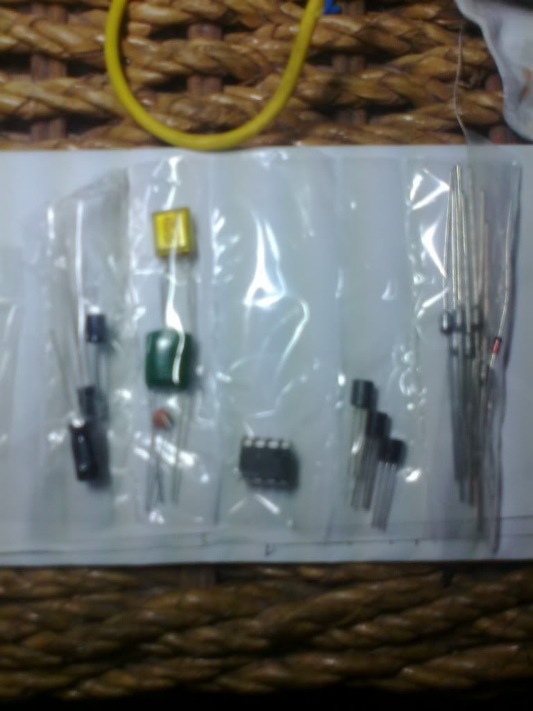
After buying all the parts, you can solder them unto your PCB or have someone with knowledge in the field do it for you.
Also, wire the harness properly
Make sure to solder ALL parts in the proper order or you'll fry the diodes(don't worry, a diode costs only P2.50 so you can always purchase extra)
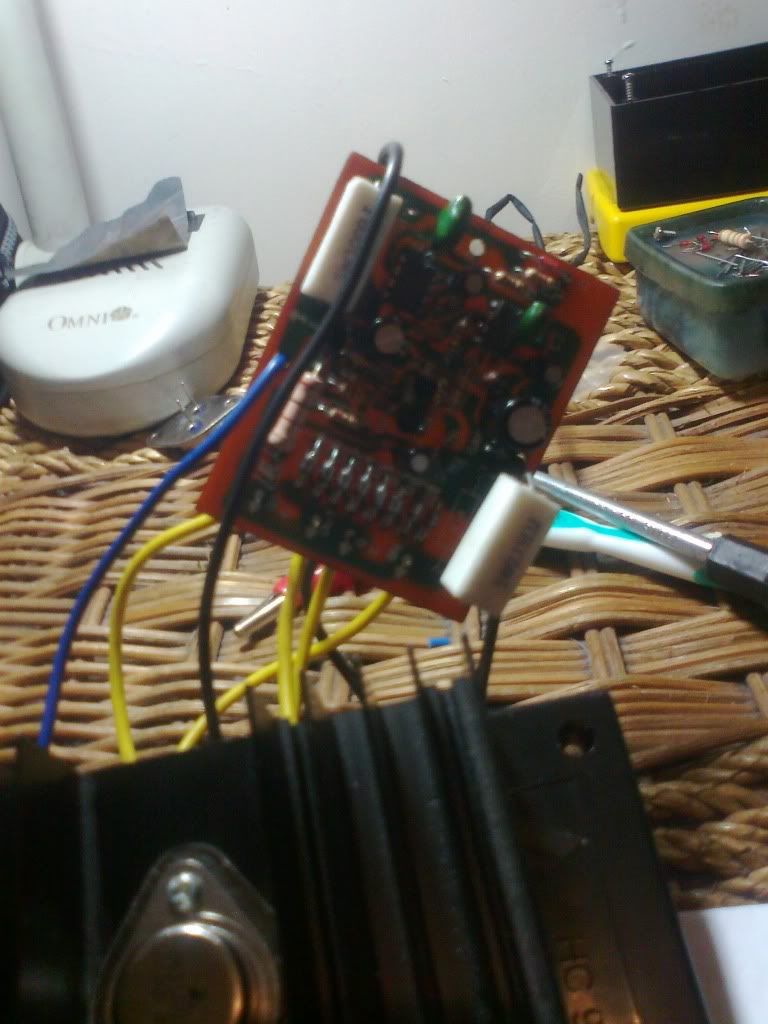
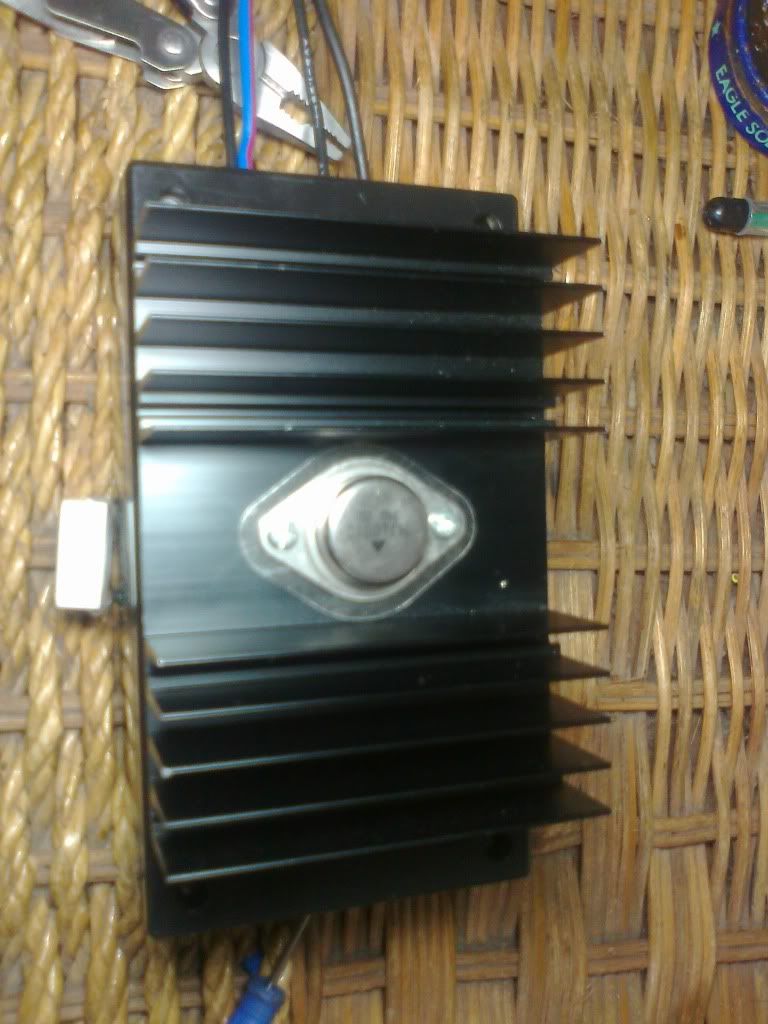
Almost finished unit.
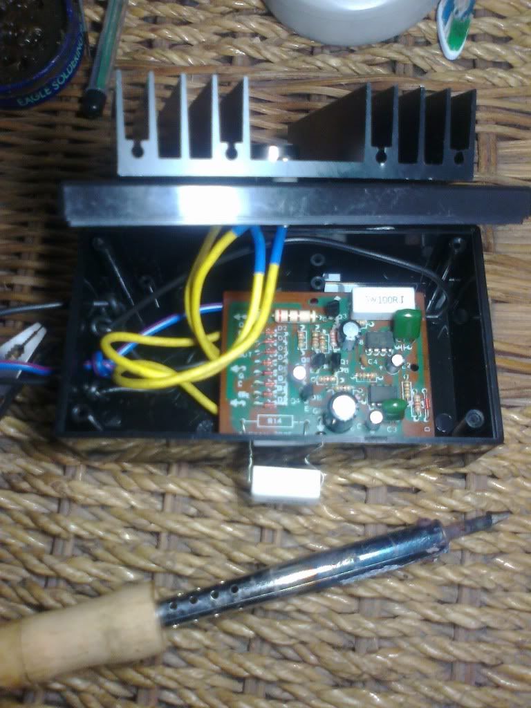
All done.
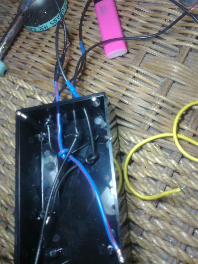
Install it in an area inside the engine bay where it won't get wet. I'll post a photo of it installed on my rig for your reference.
All in all, the whole project only cost me less than 1,2k. Not bad for an Electronic Ignition module!
I would suggest you try to purchase the "Electronic Enthusiast" volume 4 book since it is more details than the other designs. Also, this module has a 1.5ms spark timer...meaning the coil only produces a 1.5ms spark - giving it enough time to recharge thus creating high voltage sparks everytime.
Since I installed the unit, I felt an increase in power, consistent engine revs, good idle...when it comes to fuel economy, I will not comment yet on an exact figure since I am still double checking the mileage gained...but over all, I felt it can help save on petrol (since the power is maximized)
If you are into electronics stuff, then this project will be very easy for you.
You can also have someone do this for you...
If you need PCB's for these, then PM me so I can help you get in touch with JD Labs.
The Largest Car Forum in the Philippines
- Forums
- Discussions
- Events
- Community
Results 1 to 20 of 53
-
 Verified Tsikot Member

- Join Date
- Jul 2010
- Posts
- 33
June 27th, 2011 12:14 AM #1
-
 Tsikoteer
- Join Date
- Jul 2007
- Posts
- 1,245
June 27th, 2011 12:41 AM #2Very nice project. How do i contact JD labs. I have some PCB's that needs to be printed.
-
Verified Tsikot Member
- Join Date
- Jul 2010
- Posts
- 33
June 27th, 2011 01:01 AM #3Come to think of it...I don't have their number! LOL
Their office is located just across where I work so I just cross the street to get there. I'll get back to you on that...or if you want, just PM me your number & i'll give it to their tech for a follow-up call.
-
 Tsikot Member Rank 5
- Join Date
- Aug 2005
- Posts
- 7,186
-
Tsikot Member Rank 4
- Join Date
- Oct 2002
- Posts
- 2,719
June 27th, 2011 02:22 AM #5i built one CDI for my car ages ago ... the first thing i noticed was a very quick starting

-
Tsikot Member Rank 2
- Join Date
- Jun 2005
- Posts
- 3,774
June 27th, 2011 08:21 PM #6we've been using this kit for more than a decade and is installed in a 78 lancer and 1990 corolla xl. works great and helps on a starting.
i would warn you though to brush up on your electronics skills as this still requires modification. down side of this kit is it charges the ignition coil and produces a lot of heat. once the coil heats up more than it is designed, titirik kotse. ive experienced this a number of times mostly sa slex and commonwealth.
be sure to rig it with a bypass just in case masira ang electronic ignition. btw, we made about 6 of that...
-
Verified Tsikot Member
- Join Date
- Jul 2010
- Posts
- 33
June 27th, 2011 11:43 PM #7*Meledson - Try building one for it na!...Its not as hard as it looks.
*Kinyo - Where did you get the CDI layout sir? Does it have the multi-spark feature?
*Sirkosero - Thanks for the heads-up sir. Actually, I did notice the coil heating up more than usual.
Also, I do see a slight flaw in the design layout. It indicated there to bypass the ballast resistor(rated at 1.5ohms) found on the positive side of the coil. Although they added a resistor in the circuit, it only had 0.5ohms resistance & 5 watts output. This in effect, increases the current & voltage passing through the coil - giving you a bad ass spark, but pushes your coil to its limits.
The thing about ignition coils; even though it is installed in a 12volt system...it is meant to run on only 6 volts of power.(If it was made to run at 12 volts, then you wont be able to start your car since the starter eats up half of the current)...
Based on my observations, there are three ways to remedy this.
1. change the resistor in the module with one that has 1.5ohms rating.
2. Replace it with a heavy duty ignition coil.(the red Bosch coil will work just fine)
3. DO NOT bypass the ballast resistor.
For me, after noticing the heat being produced by my stock coil, I did the 3rd option. It did decrease the power output of my engine just a little bit, but made my coil cooler. I do plan to install a Bosch unit though, so I can take advantage of the added power given by the module.
How to tell if your coil is running more current than it should?
Step 1. Get a multitester or Volt meter and set it to DC. If using digital, set the max voltage to 20V.
Step 2. Hook up the positive needle to the + of the coil. Hook up the neg needle to the (-) of the coil.
Step 3. Turn ignition to ON position. It SHOULD read more or less 6V.
Step 4. Start the engine. Slowly rev the engine and watch the meter. It should rise up to 9V while your revving up the engine. If it reads more than that, your coil is biting off more than it could chew.
Do keep in mind, ignition coils are able to withstand harsh currents. They are made that way. However, it still comes down to how well each coil is made. Meaning, quality coils will be more durable while cheap ones will burn easily.
NOTE:
When acquiring Bosch coils, try to get the red one since the blue one has a resistor already built in the unit.
-
Tsikot Member Rank 2
- Join Date
- Jun 2005
- Posts
- 3,774
June 28th, 2011 12:11 AM #8imho, always get the red bosch coil. other brands conk out after a week. although the kit destroyed a couple of bosch as well, when the kit had some problems over time.
btw, the bypass i was mentioning is a wire or a switch that would let you go back to regular ignition in case some components fail.
bit OT, when u had d PCB etched, was it using the ferric chloride solution or photo etching? i saw a kit on the internet years back about a multi-spark ignition system and had the diagram and pcb design. i didnt try it since i hate masking pcb and dipping it in the solution and i dont have the photo etching thing either. btw, i think alexan at soler still sells the kit
-
Verified Tsikot Member
- Join Date
- Jul 2010
- Posts
- 33
June 28th, 2011 03:56 AM #9True, other brands(even imported ones) don't last that long.
As a matter of fact, I installed a bypass that does exactly that, except in the form of a switch...para with just a flick of the switch, back to regular ignition na siya.
I tried making PCB's before but for a different project. I already made 2 units(1 with a recycled alexan PCB and the other 1, I had it made).
Based from what I heard, I think they used a combination of both. Honestly, I didnt want to hassle myself from making my own PCB since I only needed one piece. Luckily, I was able to salvage one.
-
 Tsikoteer
- Join Date
- Mar 2008
- Posts
- 575
June 28th, 2011 11:17 AM #10Sir:
I'm very impressed with you work, tyaga mo sir!
I too am looking for someone to make PCB's for me...
Could you please PM me the address of the company that makes them?
Thanks in advance.
Best Regards,
Dusky Lim
P.S. I PM'd you with contact info...
-
Tsikot Member Rank 4
- Join Date
- Oct 2002
- Posts
- 2,719
June 28th, 2011 09:07 PM #11the CDI i built did not have multi-spark feature ... it was a very simple circuit consisting of a bjt (2 x 2N3055 plus transformer) multivibrator circuit to charge the capacitor to almost 400 volts and an scr to discharge onto the primary of ignition coil. Originally Posted by Chef Noob

-
Verified Tsikot Member
- Join Date
- Jul 2010
- Posts
- 33
June 28th, 2011 11:34 PM #12Nice design! How were you able to overcome the hard starting symptom of the CDI? Originally Posted by kinyo
I always wanted to build one myself. Unfortunately, I'm still looking into the "safety" factor - for myself & the car's sake. Getting an electric shock from a 400v CDI module just doesn't sound that appealing to me.
-
Tsikoteer
- Join Date
- Jul 2007
- Posts
- 1,245
-
Tsikot Member Rank 4
- Join Date
- Oct 2002
- Posts
- 2,719
June 29th, 2011 02:58 PM #14Not sure if i understand the question, because i did not experience "hard starting" with the CDI. It consistently starts the car quickly even on cold starts. Originally Posted by Chef Noob
Yes 400V could be a bit shocking, but it is still considered low voltage by electrical standards.
-
Verified Tsikot Member
- Join Date
- Jul 2010
- Posts
- 33
June 29th, 2011 10:54 PM #15Based on the research I done regarding CDI, it increases the voltage produced by the spark plug but shortens the spark duration considerably. This in some way, creates situation for certain engines to have a hard time starting... Originally Posted by kinyo
Although I havent witnessed it personally.
-
Tsikoteer
- Join Date
- Mar 2008
- Posts
- 575
June 29th, 2011 11:40 PM #16Hello Chef Noob:
Your work reminded me of when I opened up and copied a Nippondenso igniter (the electronic ignition of Japanese cars in the 80's) using locally sourced components from Raon.
I too had my share of problems with it, a straight copy of the design was less than satisfactory because at first I didn't insulate it well enough.
The igniter design uses a PNP to NPN overdriven switch triggered by the original contact points where the turn on current (base-to-collector) is multiple of the hfe gain.
Basically you looked up the transistor's specs - particularly the hfe and rated current it could switch, and multiplied the hfe by a factor of 5 or so.
When you do this, the transistor ceases to behave as a linear amplifier and at that point and simply becomes a high-speed switch - like the contact points themselves.
Although the design gives up a lot of gain (amplification) the excess turn-on current makes a bipolar junction transistor's internal resistance drop dramatically - typically to 0.5 to 0.1 ohm - which is the key benefit of providing excess turn-on current (aka overdrive)!
This means that when switched on and carrying the full load of the coil primary - the transistor itself has the least resistance of all the ignition circuit's components.
In this design the stock contact points only had to switch 1/150th of the original current (from carrying 10 amps to just 0.067 amps) so that they no longer pitted, only very slowly (over a year or more!) got light grey oxidation.
A smaller PNP transistor was switched by the coil and it's output drove the larger, main NPN transistor.
The 1st problem was that if you didn't insulate the main NPN power transistor (2SD458) well enough, during the switching, the coil's primary winding voltage would temporarily go to 400-600 volts at the NPN transistor's collector and this would produce shorts into the aluminum heat sink frame.
You had to use mica insulation, nylon bushings an lots of silicone grease to insulate it properly.
Still even after all that there were still problems.
Basically the main failure was due to punch-through - the transistor would break down from the extremely high collector-to-emitter voltage.
The original Nippondenso design addressed this via a voltage divider (resistors) parallel the collector-to-base-to-emitter circuit, limiting the speed at which the transistor turned on and thus reducing the induced voltage at the coil primary - reducing the tendency of the voltage to punch through.
This also reduced both the voltage and power output to the spark - the slower switching rise meant lower induced primary voltage - hence lower induced secondary voltage - and lower energy transfer from coil primary to coil secondary to boot!
After loosing several igniters to this punch-through problem, rather than copy the original Nippondenso solution (i.e. - surrender), I decided to mimic the solution of the original ignition circuit.
Here's what I did:
In the original contact point circuit the points themselves to switch the coil primary.
However the points are not the only component in that circuit there is one more thing there that if you remove will prevent the ignition circuit from working correctly.
That's the capacitor which is wired in parallel to the points.
When the points close, current flows across the coil primary, and builds up a magnetic field, storing energy that becomes the spark in the coil secondary.
When the points open, the coil produces an induced current that tries to keep flowing - the faster the points open the higher the voltage of the induced current.
If there were only the points in the coil primary circuit - the induced voltage would jump the gap and spark and burn the points.
The capacitor is there to stop that from happening.
In fact, the 1st ignition circuits (before 1920s?) put the contact points INSIDE the combustion chamber - using that induced spark to create ignition, the ignition coils of that era had no secondaries only primaries!
When the points open the capacitor stores the coil's induced voltage spike instead of allowing it to be borne completely by contact points.
This allows them to separate without too much sparking and allow the transfer of energy from coil primary to secondary.
Using this as my model I computed (very roughly) the energy stored in the coil primary and added a capacitor in parallel to the NPN circuit - effectively storing the energy and preventing punch-through.
Its been a long time since I did that.... thanks for the memories.
Best Regards,
Dusky Lim
-
Verified Tsikot Member
- Join Date
- Jul 2010
- Posts
- 33
June 30th, 2011 04:33 AM #17Thank you for the very well explained theories. I can tell by your post that you also enjoyed the time you spent doing this.
I was amazed that you were able to create primary voltage up to 600v using only transistors. Even up to now, only CDI modules are able to produce those levels of voltage. Though it may prove very beneficial for the power gains in the engine, considering the cost & wear on your parts(coil, plugs, etc.) wont be cost efficient. Even if you were able to extend the life of your power transistor, I think the plugs were not meant to handle those voltage & currents. I myself also seen a few designs where they attached the capacitor in parallel to the transistor.
Honestly, the main reason we are discussing here right now is because of this capacitor aka "condensor".
In a perfect world, if it were able to work perfectly...I think most production cars right now will still be using the points system.
Theoretically, the capacitors are able to absorb the "back EMF" created by the induced current.
In the standard points system, when the points open, the capacitor absorbs the extra spike of current thus eliminating the dreaded "gap spark". However, that power is still stored within the capacitor. The problem lies from the closing of the points. Since the charge from the capacitor have no where to go, it "grounds" itself as the points closes, creating a "mini" spark as this happens. This spark may not be that much but after doing this for atleast 1000 times a minute, that tiny spark will do damage to the point surface. (based on the laws of electrolysis)
That is why in the real world, you can still see burnt points even though the capacitor still works perfectly.
The option I'm dwelling on right now is to induce a stronger spark...not by reducing the resistance of the transistor to induce more current...but to increase the output on the coil - at the same time prevent it from over heating.
As you stated in your post above, transistors are more fragile than we think. It can easily fry when subjected to extreme currents.
However, if you increase the current on the ignition coil, you can still attain good spark from it. One problem is: What if the coil overheats? What I'm thinking of is putting a cooling system to reduce the temp of the coil. A finned heatsink perhaps? Or even water-cooled? :-)
-
Verified Tsikot Member
- Join Date
- Jul 2010
- Posts
- 33
June 30th, 2011 05:02 AM #18*Ginnova I was trying to PM you sir but it says that your Inbox is full.
-
Tsikoteer
- Join Date
- Mar 2008
- Posts
- 575
June 30th, 2011 10:44 AM #19Dear Chef Noob:
Actually I couldn't directly measure the peak primary voltage, (I don't have an oscilloscope with a high-voltage probe) but when the igniter failed, I would always check to find the cause of failure.
Consistently, I found that the main NPN power transistor had shorted out at the collector-to-emitter junction - classic failure by punch-through.
Now according to the Motorola transistor manual, the 2SD458 has a breakdown voltage of 600 volts (DC) at the collector-to-emitter junction, hence my assumption that the voltage was peaking past the transistor's limit, burning through and shorting it out.
That voltage peak is of course a transient peak voltage, created by the rapid switching of the transistor itself, while CDI ignitions can create sustained peaks of 600 volts or more - it is the duration that the voltage is sustained is the key difference between the 2 types of ignition systems, transistorized and capacitive.
Remember this equation?
V = (-) L*di/dt
<the induced voltage V is of opposite polarity and equal to the coil primary inductance L multiplied by the time rate of change di/dt of the switching current>
To reduce the heating of the coil (which is actually worse during low-rpms rather than high-rpms) you keep the ceramic ballast resistor in place - don't by-pass it!
At low-rpms the turn-on time is much longer hence there is more time and current for the coil to overheat, at high-rpms the short turn-on times effectively reduce the total current and the coil cools down rather than heats up.
The ballast resistor's resistance increases with increasing temperature, reducing the current to the coil, thus keeping it cooler at low rpms, but that resistance decreases with decreasing current at higher rpms, allowing more current to flow - it effectively behave like a current control (a little slow and crude - true) for the coil and ignition circuit.
The best choice I found was to get (2nd hand) very large coils that came with some high performance Japanese engines.
The way to test for a high power, high performance ignition coil is:
1) measure the coil primary resistance - a high power coil has very LOW primary resistance and thus will pass a lot of current and store a lot of energy
2) measure the primary-to-secondary resistance - a high power coil will have very HIGH primary-to-secondary resistance allowing it to withstand very high induced voltages
The Bosch red coil is a good example, but the huge 2nd hand Japanese coils we used back then had the lowest primary resistance I have ever measured - only 1 to 2 ohms!
We used them with ballast resistors taken from the Bosch red coils.
You are quite correct in describing how the capacitor works in a conventional points system.
We used to go a little further than this in modifying them.
We would look at the points and determine which face (moving or static) lost material and which face gained material - alin yung may uka at alin yung may bulutong.
Then you buy a capacitor with a different micro-farad rating until the transfer stopped.
All that became academic with the use of the transistorized ignitionl - point buring was no longer an issue.
However point bounce and flutter still remained - hence the move to different triggering systems.
As to the issue of coil overheating, well the Bosch red coil does tend to overheat, especially if you remove the ballast resistor - which will eventually burn it out.
The large Japanese 2nd-hand coils however, didn't overheat - they lasted as long as we had our cars.... go figure.
If you wish to cool your coil down - my vote is for an aluminum heat sink - keep water and fluids well away from your ignition system.
The ultimate in ignition systems is of course the magneto - its the only system where the spark power INCREASES with rpms. he he he.
Best Regards,
Dusky Lim
-
Verified Tsikot Member
- Join Date
- Jul 2010
- Posts
- 33
June 30th, 2011 02:22 PM #20I thought the ballast resistor installed in our cars are of the fixed type and not the self-variable ones? Originally Posted by duskylim
I always thought that the coil heating up is the cause of repetitive induced voltage created by the opening of the points...See, we learn new things everyday. :-)

 Reply With Quote