
Dear Guys:
Here's another update on what going on in my neck of the woods - Fairview.
I bit the bullet and decided to adjust the valves on my B2500 myself.
I have had it done twice before - once at Francisco motors ng bago pa siya and the 2nd time at DRT by Gener del Rosario.
To tell the truth, I wasn't satisfied with the results and so habang sinisipag pa ako I wanted the satisfaction of getting done RIGHT by myself - without having to worry if it was done correctly.
After all, I used to run a shop and do it for our Galant Sigma, Dodge Colt and Toyota Corona, as part of every tune up.
It was pretty easy for those cars, so it shouldn't be a problem on the B2500, right?
Wrong. Very, very wrong.
Wow! Napaka-hirap pala mag-adjust ng valves ng WL-engine!
To be fair the hardest part was finding out the actual valve clearances - for the WL-31 engine - they are NOT in the owner's manual and are very difficult to find even on-line.
I finally found this guy who claims to have a factory manual of the engine who gave me the figures (ones' I could believe in).
Now to the actual job of adjusting them myself.
I decided to start at about 1:30 PM this Sunday so that by 5 or 6 PM dapat tapos na lahat!
You have to remove the air-cleaner assembly, the long induction tube and of course the valve cover assembly just to get access to the parts.
My air-cleaner is more complicated to remove because of my extra air-filter assembly and water-methanol fuel and wiring lines that run along it.
The induction tube is attached on the driver's side to a stand-off plate which is bolted to the cylinder head, then to a short hose that attaches to a u-tube that goes into the intake manifold, and by 2 nuts to a frame on the passenger side of the engine.
After all that, you have to remove the glow-plugs for cleaning and so the engine's compression won't fight you when your turning it to top-dead center.
Number 2 glow plug decided to give me a problem and was very tough to remove.
I had to turn it back and forth several times and constantly spray on WD-40 to loosen up the threads.
30 minutes and 2 coffees later, No. 2 glow plug was out - as usual, the threads were choked with carbon - the main reason why they become hard to remove.
Took the plugs to the vise and power grinder and used the rotary wire brush on those fouled threads, - 15 minutes of hard brushing and voila' - just like new.
After the glow plugs, I noticed that the fan belts were loose - even by my standards, so I had to tighten them up a bit so I could use them to turn the engine to top-dead-center.
I did the A/C belt too for good measure - it seems all my belts have loosened up considerably since I last checked them ( a long, long time ago).
With the belts all snugged up, I turned to finding the timing marks on the engine's pulley - no as easy as it sounds, there are 2 timing marks on the engine and no indication as to which is the correct one.
So I opened up the cam and valve cover - 12x10 mm bolts with washers, rubber grommets and a long bushing inside each to hold down a very long and thin rubber gasket!
With the trouble light shining on to the timing marker, I slowly used a ratchet to turn the generator pulley bolt (24 mm head) until the 2 timing marks appeared, I stopped the crank at the 1st timing mark.
A glance at the camshaft revealed that the engine was at Top Dead Center for No. 1 piston, turning the crankshaft to the 2nd mark would seem to make it go too far so I decided to use the 1st mark as the TDC reference.
Another weird thing I noticed, while I was rotating the crankshaft Clockwise, the camshaft was rotating counter-clockwise - and so with the injection pump!
This baby rotates its cam and injection pump in the opposite direction to the crank! Whoagh!
Anyway back to the valve adjustment - the WL-31 is a 12-valve engine - it has 3 valves per cylinder - 2 intake valves and 1 exhaust valve in a triangular arrangement - the 2 intake valves form the base of the triangle and the exhaust valve is the apex.
It is also an overhead cam design, which means the camshaft is located above the cylinder head and actuates the valves directly this way via finger-like cam followers.
The camshaft is located at the mid-line between the intake and exhaust valves, with the cam followers pivoted on opposite sides of each valve.
That is - each intake cam follower is pivoted near the exhaust valve and the exhaust cam follower is pivoted between the 2 intake valves.
Each follower rests both on it's pivot and the valve it actuates, with the cam directly above it.
As the cam rotates it pushes a pad on the mid-point of the follower causing it and the corresponding valve to open.
On this type of engine design, it is the gap between the cam and the follower that is adjusted.
At TDC no.1 cylinder you can adjust 4 sets of valves, number 1 pair intake, number 2 pair intake, number 1 exhaust and number 3 exhaust.
At TDC no. 4 cylinder you can adjust the remaining valves.
So you only have to turn the engine around once to adjust all the valves.
Will be back tomorrow with the 2nd part of the valve adjustment.
Regards,
Dusky Lim
The Largest Car Forum in the Philippines
- Forums
- Discussions
- Events
- Community
Results 1,661 to 1,680 of 2085
-

 Tsikoteer

- Join Date
- Mar 2008
- Posts
- 575
March 20th, 2011 11:37 PM #1661
-
 Tsikoteer
- Join Date
- Feb 2009
- Posts
- 858
-
Tsikoteer
- Join Date
- Mar 2008
- Posts
- 575
March 22nd, 2011 09:03 AM #1663Dear Ronn:
No, definitely not.
I found that DRT's people adjusted the valves much too tight.
I have been adjusting valves for more than 30 years now and nobody has to show me how to do it correctly.
The reality is time and convenience are the enemy - and also my legendary katamaran.
Of course the original settings by Francisco Motors were even tighter, but I was still not satisfied with their (DRT) work.
From now on, I will adjust the valves myself - just to be sure they are right.
To make a long story shorter, I also cleaned the strainer on the injection pump before running the engine.
Fingers crossed I started her up, fired immediately and voila' - great run!
Idle is much smoother - mas makinis, although you can hear the the looser valve train in the background.
Blipping the throttle it accelerates much more crisply -lakas ng hila!
There are further benefits -
1) the engine runs cooler with the looser exhaust valves, they were probably running hot...
2) the sound of the intake (HAGOK) is much louder now - it reminds me of my old twin-down carbs on full throttle - ... he he he.
I am no fan of tight valve adjustments, intake or exhaust and most diesels prefer loose valves.
This just goes to show you have to make the extra effort (walk the extra mile) to get everything done right.
Grabe lang talaga yung hirap to get the job done right.
Luckily for me, adjustment is only needed every 20 - 30 thousand Kilometers, so it will be some time before I have to do it again.
Sorry for the long post,
Best Regards,
Dusky Lim
PS - I found that the crankshaft of the WL-31 engine drives the injection pump via a gear that is 1/2 the diameter of the gear on the injection pump.
One good thing about this is that the crankshaft and the pump are more rigidly locked together in timing compared to the use of a belt.
The whole thing is more complicated and expensive.
The result is the pump turns at half the speed of the crankshaft and rotates in the OPPOSITE direction.
The Mazda engineers decided to drive the overhead camshaft from a timing belt attached to the injection pump drive, so both the pump and camshaft turn at 1/2 engine speed, and both rotate in the opposite direction.
I speculate that this was originally a pushrod-type overhead valve engine that they converted into a overhead cam type design.Last edited by duskylim; March 22nd, 2011 at 09:15 AM.
-
 Tsikoteer
- Join Date
- May 2009
- Posts
- 1,990
March 22nd, 2011 09:47 AM #1664Sir, Originally Posted by duskylim

You have 2 idler gears in between the crankshaft timing gear and the injection pump pulley the reason why the IP and cam rotates ccw if the crankshaft rotates cw. You may want to have the rebuild manual sir. Just pm me.
-
Tsikoteer
- Join Date
- Mar 2008
- Posts
- 575
March 22nd, 2011 02:56 PM #1665Dear Sir mike: Originally Posted by miked
I am definitely interested in a copy of the rebuild manual, PM was sent.
Thank you very much, I appreciate the offer.
More power to you, Keep on Trucking!
Best Regards,
Dusky Lim
-
Tsikoteer
- Join Date
- May 2009
- Posts
- 1,990
March 23rd, 2011 11:28 AM #1666Attaching file as of this writing....mejo malaki yung pdf file. kindly check......
enjoy reading......
-
Tsikoteer
- Join Date
- May 2009
- Posts
- 1,990
-
Tsikoteer
- Join Date
- Mar 2008
- Posts
- 575
March 23rd, 2011 03:27 PM #1668Dear Sir Mike:
Maraming, maraming salamat po!
Your kindness will be rewarded!
Thanks again!
Regards,
Dusky Lim
P.S. Sir you might want to attend our EB sa Mazda B2200/B2500 club.
PPS - Ronn kelan kaya yun?
-
Tsikoteer
- Join Date
- Feb 2009
- Posts
- 858
-
Tsikoteer
- Join Date
- Mar 2008
- Posts
- 575
March 24th, 2011 11:38 AM #1670Dear Ronn: Originally Posted by azzkkr2600
Oo nga, tahimik na tahimik ang lahat.
Wow! Silent Night - ahem, Silent Forum.
Dear miked:
If you happen to find yourself in the Fairview area, please look me up, I live in Don Jose Subd, very near Mercury Drugstore.
My cellphone number is 0916 549 8306
Text me if you happen to be around and I will provide you with a free sample of my diesel fuel additive.
Sincerely,
Dusky Lim
-
Tsikoteer
- Join Date
- May 2009
- Posts
- 1,990
March 24th, 2011 02:18 PM #1671Salamat sa offer sir...one thing is that i don't own yet a mazda pickup....still in search while applying and waiting for some little loan. dati kasi type ko kunin isuzu fuego na 2nd hand pero i think i would settle down with a B22. marami na rin kasi ako nakita na dati kakarag-karag pero one binigyan mo ng TLC preskong-presko uli..anyway, my daily driver is a mighty max pickup (mitsu).hehe Originally Posted by duskylim
-
Verified Tsikot Member
- Join Date
- Oct 2010
- Posts
- 49
March 24th, 2011 05:56 PM #1672mga sirs!
i vote march 27 for our next EB. medyo mtagal na rin po last EB ntin.
naibyahe ko na nga pala B25 ko just last week sa Baguio to attend a burial ceremony of an uncle of my wife.
this is my first long drive since i bought my truck sometimes last year.
kwento ko nlang in our next EB comment ko sa ride ko with sir Dusky's diesel fuel additive.
vote na kayo guys! dali!!!
enjoy trucking & ingaaat!
pickupbike
-
Verified Tsikot Member
- Join Date
- Feb 2007
- Posts
- 14
March 25th, 2011 06:26 AM #1673bro dusky and all;
tnx for the reply.. i want to post my rig but don't know how. another questions mga bro, please advice;
is it advisable po ba buy ako ng second hand compressor? ilang beses na kasi na repair yun, yung aircon di na lumalamig.
yung diesel gauge meter po di na rin gumagana.
tumitirik na rin po ang makina, dont know why napaka poor ng explanation ng erpat ko, last time na nakausap ko sya maayus pa nman then nalaman ko 3 times na tumirik
meron pa po bang available sa market ng campershell? balak ko kc lagyan yung ride ko, at lagyan ng aircon sa likod? pwede ba yung ganitong configuration? malaki na kasi family..hehe extended family pala, di ko pa kayang bumili ng kapalit na van.
salamat po ulit sa advise
-
Verified Tsikot Member
- Join Date
- Feb 2007
- Posts
- 14
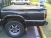
March 25th, 2011 06:42 AM #1674[IMG]http://www.flickr.com/photos/49661989*N00/5557044196/[/IMG]
please comment on my rig. Thanks!
-
Verified Tsikot Member
- Join Date
- Feb 2007
- Posts
- 14
-
Tsikoteer
- Join Date
- May 2009
- Posts
- 1,990
March 25th, 2011 11:08 AM #1676walang anuman Originally Posted by khelvin
Last edited by miked; March 25th, 2011 at 11:19 AM.
-
Tsikoteer
- Join Date
- May 2009
- Posts
- 1,990
March 25th, 2011 11:35 AM #1677Mukhang naexcite ng husto si sir dusky at prinint na agad yung manual at nageenjoy sa pagbabasa at kinalimutan muna ang thread na ito...hehe

-
Tsikoteer
- Join Date
- Mar 2008
- Posts
- 575
March 27th, 2011 11:35 AM #1678Dear Guys:
Medyo naging busy ako lately - again!!!
Sunod-sunod ang mga problema.
Na-virus or na-hack ang akin e-mail.
God knows why, as I do not have any sensitive info on it.
miked - the additive works with any diesel engine, Mazda or not. the performance is more noticeable in manual transmission vs automatics - I have found they tend to mask the behavior a lot.
khelvin - I agreed with mike - don't get 2nd hand compressors - there is no warranttee and if you get lemon you're stuck with it - and out a lot of money to boot.
the gauge problem is definitely electrical, you have to get a good electrician to look at it - na-Ondoy ba sya?
as to the engine problem, how exactly did it die? slowly with a lot of drama, or quickly? that will give you many clues as to what is going wrong.
campershells are still available from the original manufacturer - its along Banawe street near the corner of N. Amoranto. I happen to know the owner - Mario Diaz.
Unfortunately he is retired now and no longer runs the business - its his daughter in charge - at hindi nya ako kilala.
I don't recommend air-conditioning the space in the back of the campershell - what they used to do is REMOVE the rear windshield so that your existing A/C blows all the way to the back and seal the edges with a rubber bellows - but it doesn't really cool the back that well and your A/C and engine will becomes stressed trying to cool it.
If you have spent a long time in the back of a pickup you will know that its close to torture, so why bother to A/C it?
Guys - can't make it on March 27 as may burol na naman akong pupuntahan.
Best Regards,
Dusky Lim
-
Tsikoteer
- Join Date
- Feb 2009
- Posts
- 858
March 28th, 2011 03:01 PM #1679 Originally Posted by khelvin
sir, it's reporting as a private photo. you can try uploading your photos at www.photobucket.com
thanks!
-
 Verified Tsikot Member
- Join Date
- Mar 2008
- Posts
- 67
March 28th, 2011 07:43 PM #1680sirs;
have you checked this site ..http://www.mazdabscene.com
more power

 Reply With Quote