
Disclaimer: This write-up is for informational purposes only. Author will not be responsible for any damage to parts or physical injury if ever others would try to follow the steps stated here.
Procedures done for this write-up may not be the best of all procedures. Others may state also their methods. It's a forum.
This may require minimal mechanical and technical skills.
Tools for the job includes your basic/common wrenches and screwdrivers, a simple multimeter (continuity/diode test), a workbench with a vice (of course), plastic hammer, soldering gun (about 100W) and soldering pump.
First, of course, is to "divorce" the alternator from the engine. For some diesels, remove the vacuum pump from the rear of the alternator.
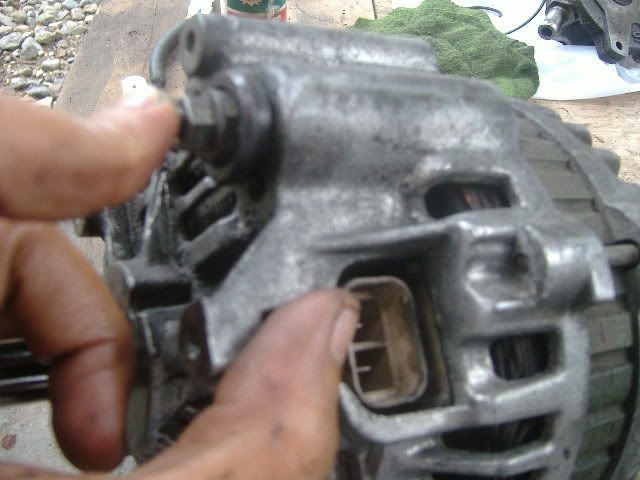
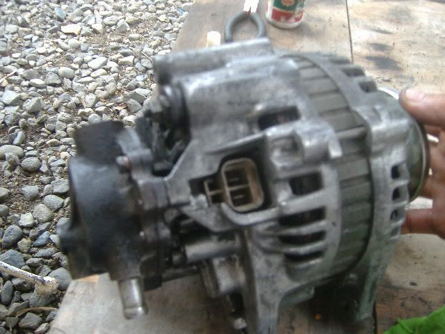
Alternator involved is a mitsubishi 12 volts, 75 ampere married to a 4d56 turbocharged engine. Picture below shows the battery charging terminal (pointer finger)and the lamp and sender terminals (thumb).
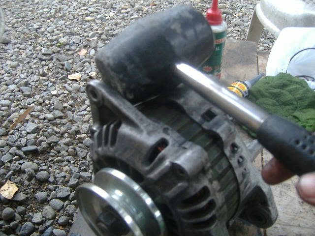
Remove the long through-bolts and knock gently through the ears.
It also helps if you have the manual for some specific tests later on
The Largest Car Forum in the Philippines
- Forums
- Discussions
- Events
- Community
Results 1 to 5 of 5
-

 Tsikoteer

- Join Date
- May 2009
- Posts
- 1,990
November 13th, 2011 02:13 AM #1
-
Tsikoteer
- Join Date
- May 2009
- Posts
- 1,990
November 13th, 2011 02:39 AM #2An alternator basically have the ff parts: rotor, stator and the voltage regulation unit. for compact alternators like this one, the VR unit is inside the alternator. for older types, you have an external VR.
How to produce electricity? Just review your grade school or high school physics. It says something like using a moving magnet and a stationary magnet and then the electrons move here and there, etc. It also depends on the speed of cutting through the field generated by the magnet and so on......get it?
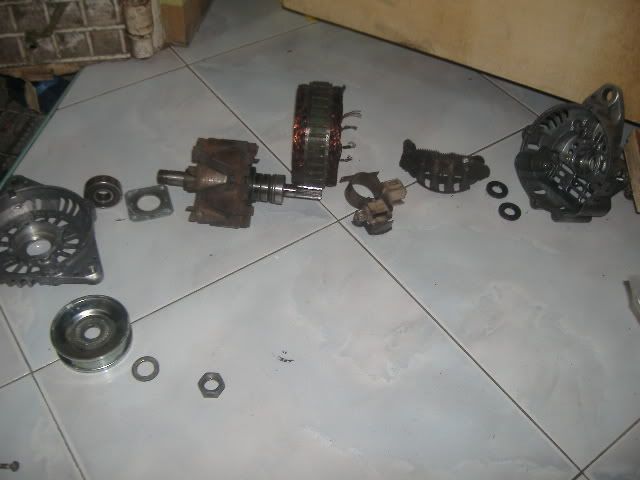
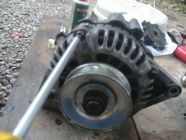
Left of the picture shows the rotor driven via a pulley and at the right is your stator and the VR unit or what we usually call the integrated circuit (IC).
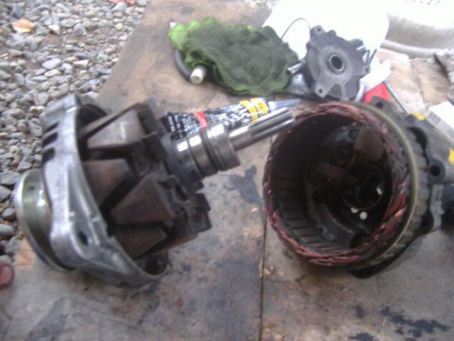
So-called electrical specialists usually use solvents or gasoline to wash alternator parts. to those who may not know it, gasoline actually damages electrical parts especially the VR unit.
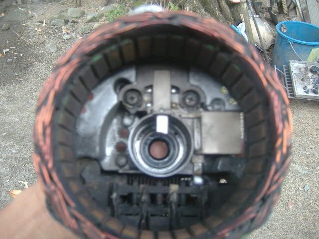
Pic shows the stator, rectifier assembly and the VR/IC unit.
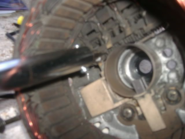
Now, unsolder the stator-to-rectifier connections as quickly as possible. Unsolder also the rectifier-IC connection. I used a 100W soldering gun and a soldering iron. The soldering gun gains heat faster but loses heat at the same rate too due to its thinner heating tip as compared to the iron. Caution on the usage of soldering tools. Heat is the primary enemy of electronic parts.
Inspection of the alternator guts consists of the the ff: continuity and ground tests on the rotor and stator plus a visual inspection of the carbon brushes (if worn out) and VR unit (if cracked).
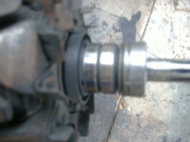
This one shows the slip rings where the carbon brushes "brush". if these rings are worn, the whole rotor assembly is replaced. AFAIK, there are no slip ring replacements. they come with the rotor.
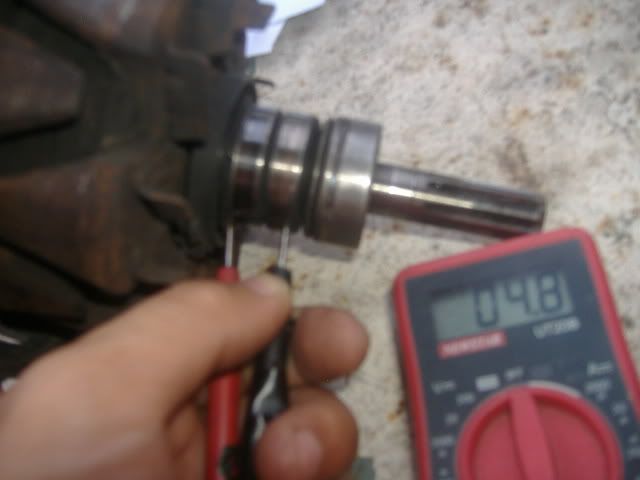
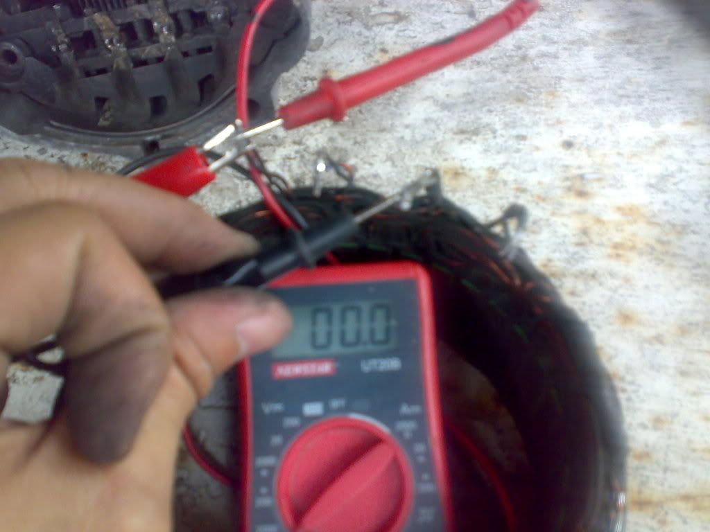
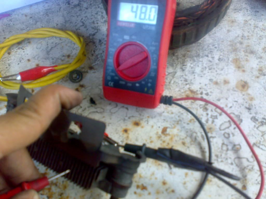
Rotor slip rings continuity tests shows 4.8 ohms minus .4 ohms of meter resistance, i.e. 4.4 ohms. Manual says 2-5 ohms continuity. So this rotor checks out fine. if less than 2 ohms, slip rings grounded. if greater than 5 ohms, an open circuit. either way, replace the rotor.
You may want to replace too the front and rear bearings where the rotor rides on. Grip the rotor with a vice to facilitate removal of the pulley and front cover housing where the front bearing resides. Removal of the front bearing is very easy using a socket and a hammer. Use a heavy cloth or wood between the vice' jaws and the rotor to protect the rotor. the rear bearing is just behind the 2 slip rings shown in the previous picture. use a bearing adapter/splitter for this one.
-
Tsikoteer
- Join Date
- May 2009
- Posts
- 1,990
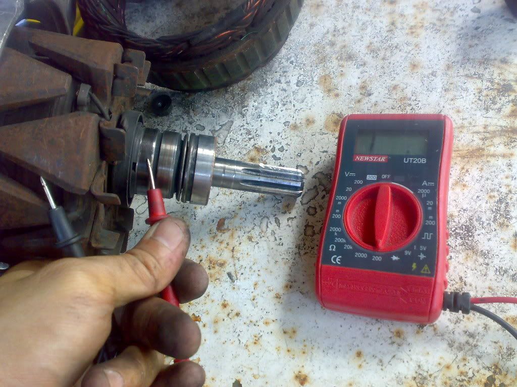
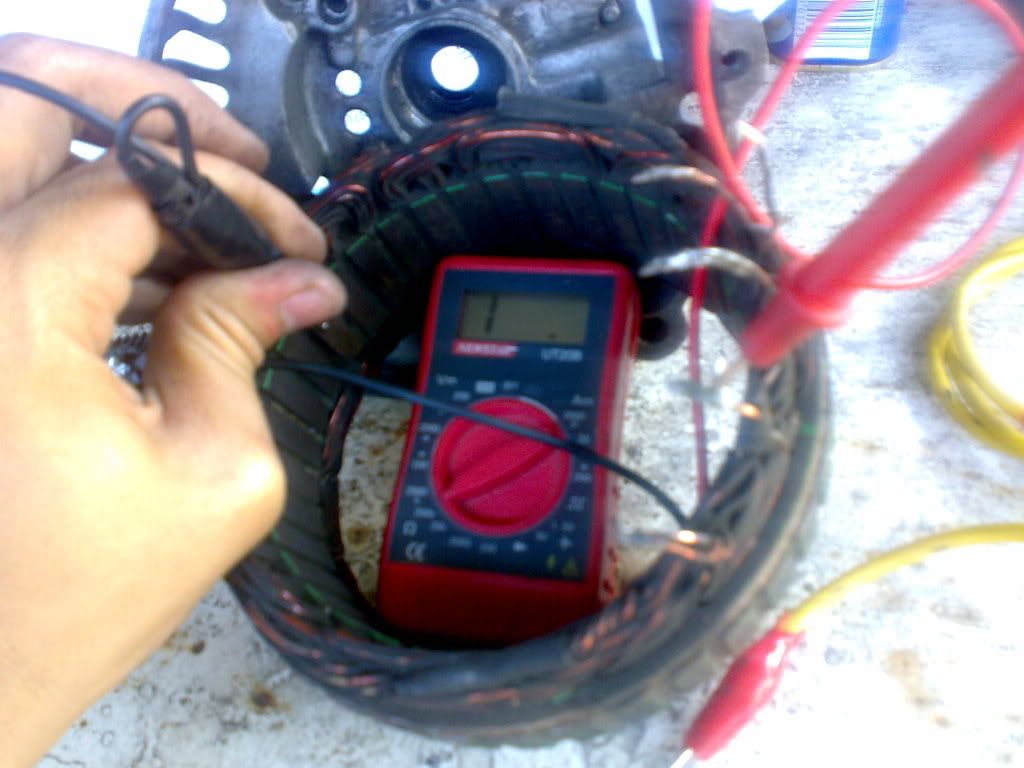
November 13th, 2011 02:56 AM #3Continuity test on slip ring to rotor core checks out fine (no continuity)
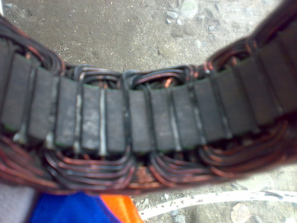
Upon removal of the soldered connections, inspect the ff on the stator core:
1. Burned windings (black)
2. Chipped varnish coating
3. Missing/burned rubber insulation on the windings passing through the core (see pic below)
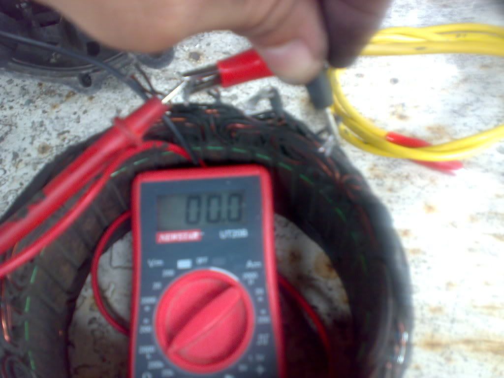
Next is to check for contintuity between stator winding leads. Every circuit must be continuous (zero ohms).
Ground check on stator winding to core.
-
Tsikoteer
- Join Date
- May 2009
- Posts
- 1,990
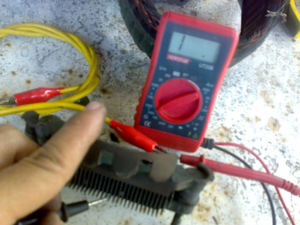
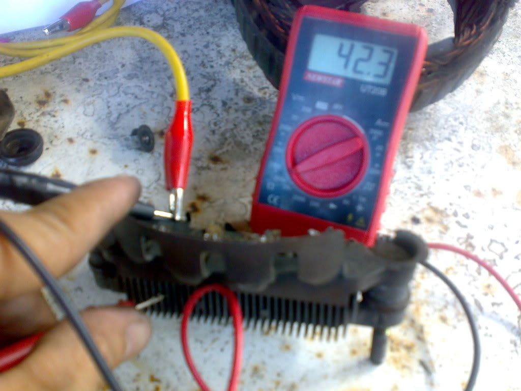
November 13th, 2011 03:04 AM #4Rectifier testing involves the positive lead on one end of the diode and the negative on the other side. If it read a low reading on this setup, it must read a high value if the meter's leads are reversed. diodes are good if they behave this way.
Now check the IC/VR unit for cracks. Replace if cracked
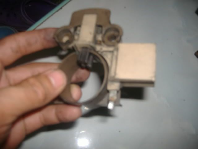
Check also the length of the brushes. Unsolder the pigtail connections quickly and replace with new ones if worn out.
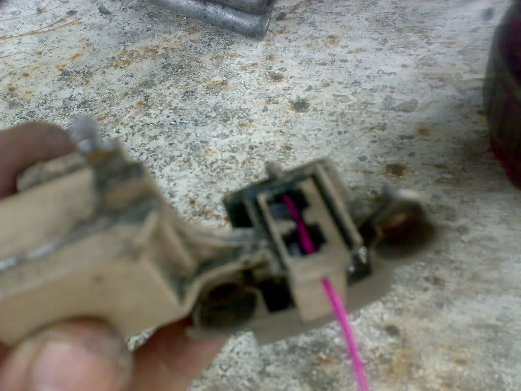
here is the "paperclip technique" used to hold the brushes in position while soldering and before inserting the rotor shaft.
-
Tsikoteer
- Join Date
- May 2009
- Posts
- 1,990
November 13th, 2011 03:19 AM #5If you encountered burned insulation, chipped varnish coating, cracked IC, like the alternator involved in this write up, better go surplus or trade it in with a reman unit as a cheaper and way lot easier route.
So here is the exploded view of the alternator. Starting from the right (order of install): Rear housing, 2 pcs oil seals, diode assy, VR unit, stator, rotor, front bearing retainer, front bearing, front housing, pulley, lock washer and nut. some may include spacers in between housing and pulley.
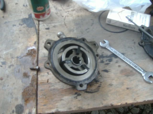
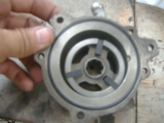
Rebuilding the vacuum pumps (diesels) is very easy. just replace the 2 pieces of O-rings and some copper gaskets. One on the front housing of the vacuum pump where it mates to the rear of the alternator. The other one is the bigger O-ring in between the rear and front pump housing (see pic). Copper gaskets on the check valve and oil supply and return lines.
Enjoy and HTH.

 Reply With Quote