


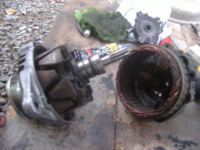
An alternator basically have the ff parts: rotor, stator and the voltage regulation unit. for compact alternators like this one, the VR unit is inside the alternator. for older types, you have an external VR.
How to produce electricity? Just review your grade school or high school physics. It says something like using a moving magnet and a stationary magnet and then the electrons move here and there, etc. It also depends on the speed of cutting through the field generated by the magnet and so on......get it?
Left of the picture shows the rotor driven via a pulley and at the right is your stator and the VR unit or what we usually call the integrated circuit (IC).
So-called electrical specialists usually use solvents or gasoline to wash alternator parts. to those who may not know it, gasoline actually damages electrical parts especially the VR unit.
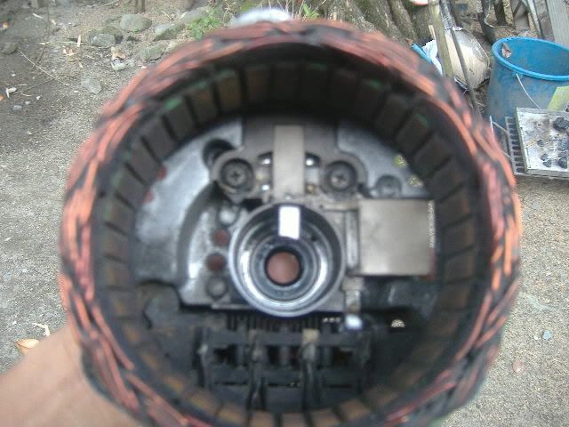
Pic shows the stator, rectifier assembly and the VR/IC unit.
Now, unsolder the stator-to-rectifier connections as quickly as possible. Unsolder also the rectifier-IC connection. I used a 100W soldering gun and a soldering iron. The soldering gun gains heat faster but loses heat at the same rate too due to its thinner heating tip as compared to the iron. Caution on the usage of soldering tools. Heat is the primary enemy of electronic parts.
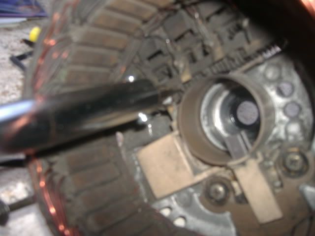
Inspection of the alternator guts consists of the the ff: continuity and ground tests on the rotor and stator plus a visual inspection of the carbon brushes (if worn out) and VR unit (if cracked).
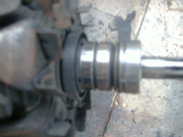
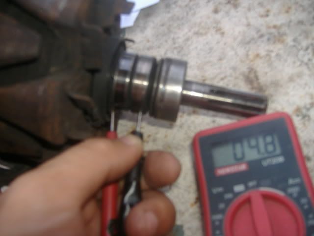
This one shows the slip rings where the carbon brushes "brush". if these rings are worn, the whole rotor assembly is replaced. AFAIK, there are no slip ring replacements. they come with the rotor.
Rotor slip rings continuity tests shows 4.8 ohms minus .4 ohms of meter resistance, i.e. 4.4 ohms. Manual says 2-5 ohms continuity. So this rotor checks out fine. if less than 2 ohms, slip rings grounded. if greater than 5 ohms, an open circuit. either way, replace the rotor.
You may want to replace too the front and rear bearings where the rotor rides on. Grip the rotor with a vice to facilitate removal of the pulley and front cover housing where the front bearing resides. Removal of the front bearing is very easy using a socket and a hammer. Use a heavy cloth or wood between the vice' jaws and the rotor to protect the rotor. the rear bearing is just behind the 2 slip rings shown in the previous picture. use a bearing adapter/splitter for this one.
The Largest Car Forum in the Philippines
- Forums
- Discussions
- Events
- Community
Results 1 to 5 of 5
Hybrid View
-

 Tsikoteer

- Join Date
- May 2009
- Posts
- 1,990
November 13th, 2011 02:39 AM #1

 Reply With Quote